Convert Cartoons / Comics or Any Raster Image with Variable Width Strokes or Borders to Vector, Using Inkscape
Originally hosted at http://forum.inkscapecommunity.com/index.php?action=articles;sa=view;article=49.
This tutorial covers 2 ways to convert cartoons/comics to vector -- trace with Inkscape's Pen/Bezier tool and auto-trace with Inkscape's Trace Bitmap. It's written with version 0.91 and can only be used with 0.91 and higher, for using the Pen/Bezier tool. But for Trace Bitmap, can be used with any version of Inkscape.
Instead of sketching a cartoon/comic on paper, and scanning it in to your computer, where you need to convert to vector, you could sketch it directly into Inkscape, as original vector paths, using a graphics tablet with Inkscape's Calligraphy tool. A graphics tablet is a separate piece of hardware, and not the same thing as an iPad type of tablet. It comes with a pen which acts like the mouse. You could sketch into Inkscape with a regular mouse, but the tablet device has pressure sensitivity, which allows your pen strokes to look more like they are drawn on paper. Often that gives a lot of character to the cartoon or comic.
Pen / Bezier tool
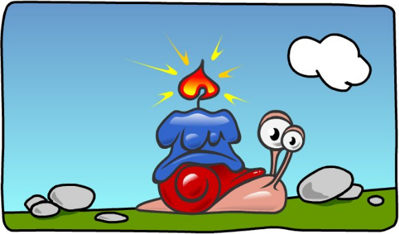
But with some patience, you can achieve something similar with just a regular mouse, and the LPE called Power Stroke. And since I don't actually have a tablet (or sketching skills) I'll use the following cartoon to explain the basics of tracing an image which has variable stroke widths, with the Pen/Bezier tool.
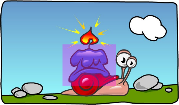
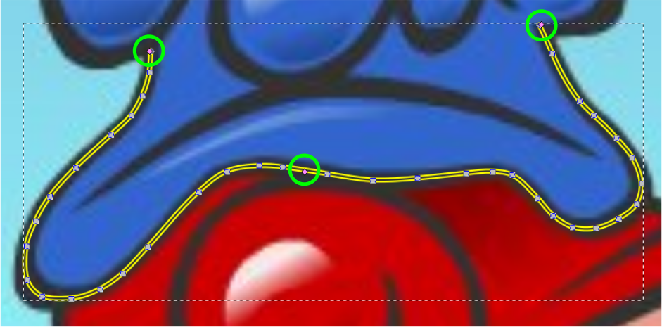
Note that the pink square isn't part of the image. That's just there to indicate the area we'll focus on for this tutorial.
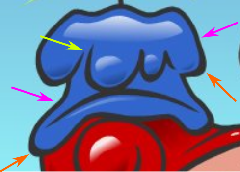
Notice the black outline/border where the pink arrows are pointing, above, compared to where the orange arrows are pointing. The border is much narrower at the pink arrows, and much wider at the orange arrows. And notice where the yellow arrow is pointing. Those lines actually comes to a point at the end.
So that's why a regular stroke with a fixed width doesn't work, for hand tracing this kind of image. Fortunately, Inkscape has a great tool for this. But first, let's get the image imported and ready to trace.
- File menu > Import
For this particular image, I'll use the default rendering mode for raster images (auto). Because of the nice black borders, I can see the details better, this way. (For other images, without the bold borders, I might use the Blocky (optimize speed) option, because it will show the pixels when zoomed in. Seeing the pixels helps to identify the color changes, when there's not a nice dark line to follow.)
Optionally, you may want to put the image in its own layer. This allows it to be locked, to prevent accidentally moving it. Also, you can reduce the opacity of the layer, which you might find helpful during the tracing process.)
- Layers menu > Layers
- Click the blue plus sign (
 )
) - Enter a name for the layer (if you want something besides "Layer 2"), and choose Below Current, from the dropdown Position menu
- Click the Add button
- Select the imported image
- Hold the Shift key while you press PdDn once (moves the image into the new layer)
- Click the tiny open lock icon (changes to a closed lock icon) to lock the layer
- Drag the Opacity slider, to suit your needs
There are a couple of ways to give the path a variable width:
- The Power Stroke LPE (new in version 0.91) and
- Pattern Along Path
Pattern Along Path generally can make a path wider at one end than the other. Because these paths get wider and then narrower and wider and narrower, etc., PAP is probably not the best solution. It could be used, but it would be very tedious. So Power Stroke would be a much better choice.
There are 2 ways to start, when you're planning to use Power Stroke.
- Draw a regular path first, then apply Power Stroke LPE, or
- draw the path using the Pen/Bezier or Pencil/Freehand tool, with Triangle In or Triangle Out option from the Shape dropdown menu on the control bar.
The latter applies the Power Stroke automatically to those paths. However, it only makes 1 control node. When the LPE is applied after the path is drawn, it adds more than one control node (usually 3). But since control nodes can be added (or removed) as needed, it doesn't really matter which way you do it. In this case, I'm going to apply it after I finish drawing the path.
- File menu > Save As
Always save new files early after you start drawing, and save often throughout the process.
- If you created a new layer for the imported raster image, click on Layer1 in the Layers dialog, to activate that layer
- Enable the Pen/Bezier tool
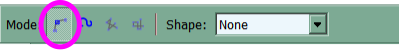
- Look on the control bar, and make sure it's in Regular Bezier mode (the circled button in the screenshot below), and that the Shape dropdown menu is set to None (like below)
- Zoom in as far as you need, to see the path well, that you plan to trace
- Position your mouse over one end of a black outline, where you want to start tracing
- Click once to start drawing a path
- Move your mouse some distance along the outline, and click once, in every place where you want to place a node
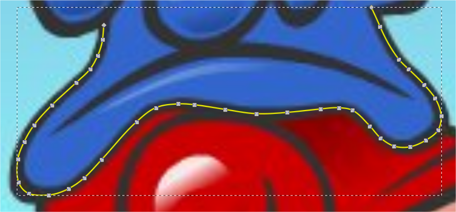
Be sure to place the nodes in the middle of the black line (not on the inside edge and not on the outside edge, but right in the middle) as shown above.
- When you come to the end of the outline, double-click to end the path.
When you double-click, you'll see that path that you've been drawing appear as a 1 pixel wide black stroke.
If you didn't place the imported raster image in its own layer, and reduce the opacity, you'll probably want to temporarily make your path white, or at least some light color, so you can see it against the black borders which you're tracing over. To do that, hold the Shift key while you click on the white block, in the palette below the canvas.
- Switch to the Node tool
- Ctrl + a (select all)
- Click "Make selected nodes smooth" button (
 ) on the control bar
Now you should have something like the screenshot above.
- Path menu > Path Effects > Power Stroke > Add
After you click Add, you'll see some new options appear in the Path Effects editor.
- In the Start Cap and End Cap dropdown menus, choose Butt
Now it should look like below. Notice the pink nodes? They're hard to see, even on your own canvas. The ones at the beginning and end of the path partially or sometimes entirely overlap the end nodes there. I've put bright green circles around them below.
- Grab the pink nodes (one at a time) and drag until the Power Stroke fits the black borders you're tracing
Since there are only 3 pink nodes, you probably won't be able to make the Power Stroke fit this black border very closely, because there aren't enough nodes.
- Position the Node tool pointer over one of the pink nodes, and hold the Ctrl key while you click once
- Drag that node away
When you drag it away, you will see the original control node is underneath.
- Drag the new control node to one of the places on the black border where you need it to be wider or narrower
- Repeat as needed, until you have enough control nodes to make your Power Stroke fit the variable-width black border
If you should need to remove a control node, it's Ctrl + Alt + click. Here's how my result looks below. Because the pink nodes are so hard to see, I've put the green circles around them again.
(If you were sketching this with a graphics tablet, the Calligraphy tool, together with your own artistic skill, would be creating the variable-width path/stroke automatically.)
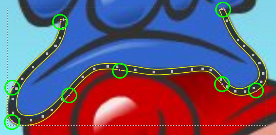
Once you make the Power Stroke wider, you may notice that you didn't get the regular nodes exactly in the middle of the black border. That can still be fixed easily by dragging the regular nodes as needed (or nudging using keys). At this point, the ends of the power stroke still don't fit the black border, but we'll be fixing that next.
Make sure that the Power Stroke is as close to perfect as you can get it (except for the ends) before moving on (because after this, the Power Stroke will be gone, and can't be brought back).
- With the Power Stroke selected, do Path menu > Object to Path
- Path menu > Simplify
- Switch to the Node tool, if not already
- Ctrl + a
- Hold the Shift key while you click the 3 or 4 nodes at the ends (to deselect them)
- Click "Make selected nodes smooth" button on the control bar
And now it should look something like below.
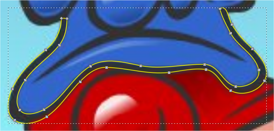
Now you can drag the nodes at the left end of the border, and fix them to match the border in the image. On the right end, you can break the path, to prepare it to connect to the top part of the cartoon candle's black border (which I haven't actually drawn here).
If you need to learn more about how to break paths and join paths, please see these tutorials: "Convert Maps, or Any Image with Fixed Width Strokes or Borders, to Vector", or "Convert Your Single Line Sketch to Vector, to Prepare for Etching", or "Convert Your Single Line Sketch to Vector, to Prepare for Cutting".
Those are the basics for drawing variable-width paths. When you're finished, of course you'll want to give them a black fill, and either a black stroke, or remove the stroke. You can either use the palette below the canvas, or Object menu > Fill and Stroke.
Adding Color
When all the black borders are finished, you'll want to use the Paint Bucket tool ![]() to apply the other colors. After you enable it, look on the control bar for the Grow/Shrink setting. For this image, I'd probably set around 0.80, give or take a couple of 0.10 (tenths). You can set it for whatever is needed for your image. If you don't set a positive number (or big enough number) you'll see a thin strip between the color and the black borders, where there's no color.
to apply the other colors. After you enable it, look on the control bar for the Grow/Shrink setting. For this image, I'd probably set around 0.80, give or take a couple of 0.10 (tenths). You can set it for whatever is needed for your image. If you don't set a positive number (or big enough number) you'll see a thin strip between the color and the black borders, where there's no color.
In this image, the black borders are quite thick, so you probably won't need to do any additional tweaking. But for images where the black borders are thin, it will be hard to find a Grow value which covers the area between the color and the border, without having some areas (where there are sharp curves or acute corners), where the color leaks out beyond the black border.
If that happens, you can use the Node tool, and drag individual nodes, or node handles, to adjust the color path so it fits well. If you need help with that, please feel free to post a message in the forum.
Some of the color in this original image is provided with gradients. It's beyond the goal of this tutorial, to explain everything about creating and editing gradients. Hopefully we'll have another tutorial about gradients, in the near future. But until then, you can find info in the manual, which is Help menu > Inkscape manual (with internet connection). Or of course you can always post a message in the forum.
Auto-Trace with Trace Bitmap
Cartoons/comics could also be converted to vector, using Inkscape's Trace Bitmap feature, or other auto-trace engine. Although the success depends on the quality and content of each particular image. Generally auto-tracing only works on the highest quality and highest resolution images, which are not pixelated and have no gradients. For this image, it's the gradients that make it a poor candidate (although there is some pixelation in the dark blue and dark red areas).
Let's try it using the same image, so you can see why.
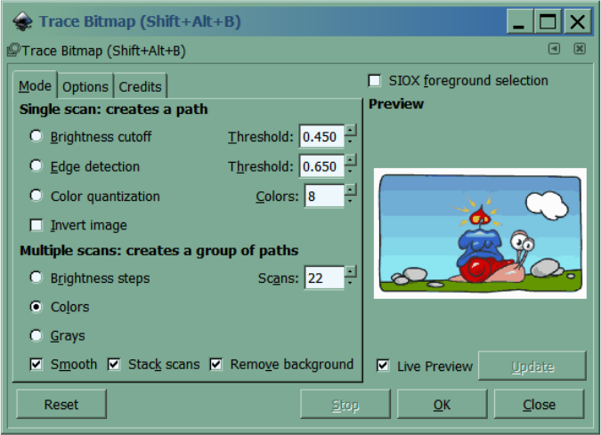
Below are the settings needed in the Trace Bitmap dialog. To make the result look as much like the original as possible, we need to use the Multiple Scan option, Colors.
Even in the Preview, you can see what happens to the gradient used for the sky. Results further below.
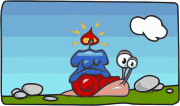
As you can see, some parts of this image were converted relatively successfully. The cloud, the ground (grass?), and the rocks look pretty close. But you can see that the gradients can't be converted at all, in any relatively successful way. So any cartoon/comic containing gradient fills can't be converted via auto-trace.
Let's say though, that your comic doesn't have any gradients, and you're still considering to use an auto-trace engine to convert it. Here are a couple of close-up views of the rocks in the bottom-right corner of the image.
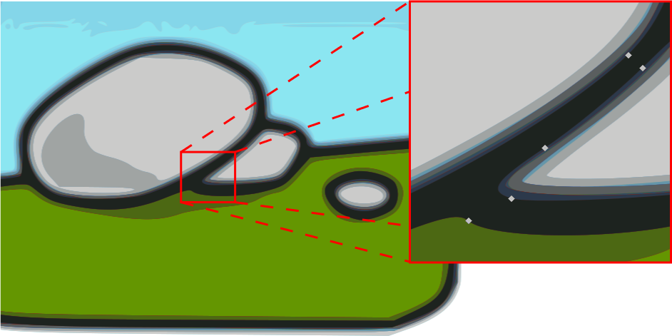
It looks very different from the view at 100% zoom, doesn't it? Even though there are only approx 10 basic colors in that image (ignoring the gradients), because of how the trace engine works, it took 22 scans/colors to come close to the original. This cartoon image is attached at the bottom of this tutorial, so you can experiment with it yourself.
In the super-closeup view of the black lines, above-right, you can see that the black objects (lines) from the auto-trace are very similar to the variable-width lines we created with Power Stroke. So that's a good thing! But we have 10 or 12 objects/colors to get rid of, if we want to use auto-trace. Here's how to start.
- After you do the trace, the results will be a Group of however many scans you set, and it will be right on top of the original image. Grab the results (with Selection tool) and drag them away from the original, just to prevent confusion later.
- Object menu > Ungroup (or this button on the command bar, or use the key shortcut (look it up in Help menu > Key and Mouse Ref).
- Zoom into an area like in the red square above, so you can see the different colors/objects more easily.
- Switch to the Node tool. Position the mouse over either the black object or the darkest object. (The black or darkest object is always on top, in auto-trace results.)
- Click once (selects the top object, which in this case is the black or darkest object).
- Hold the Alt key while you click once more (selects the next object below)
Here's what that next object below the black one is, in this image (with 22 scans) -- a reddish brown object. I gave it a bright green stroke, just to help you see it better, but that's not part of the trace results. In the pink circle, is where I have my mouse positioned.
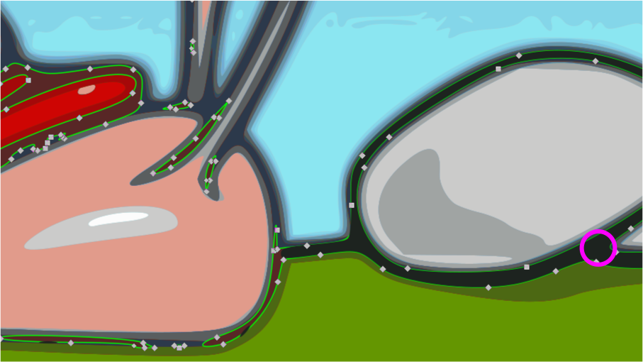
You can see that the black, variable-width line in the trace result does not cover everywhere the black line in the original image is. It's because of how auto-trace engines "see" the image, which is a result of the quality of the original (probably the pixelation in the dark red and dark blue areas). If we had used more and more scans, maybe upto 40 or 50, we might eventually see a black line everywhere it's supposed to be. But then we'd have a very thin black line, with progressively lighter, as well as progressively wider, shades of gray, stacked below. Try it, if you like, with 40 or 50 scans, and look to see what happens with the top, black line.
Anyway, in this case, the next object below the black one, is a reddish brown object, which forms the place where the black line should be, around the red and pink parts of the original image. What we need to do, is combine it with the black line.
- Select both the black and the reddish-brown objects. (Click once on the black, hold Alt and Shift keys, and click once more.)
- Path menu > Combine
Now, if you zoom out and look at your results, we have the black object covering more of the area shown in the original. But still not completely. Zoom back in.
- Repeat steps 7 and 8, to select the next object below and combine with the black one.
Zoom out, and look again at your results. It looks to me like we've pretty much got our black, variable-width line covering all the places shown in the original. From here on, use the same process, Alt + click, to select the next object down. Look to see whether it's an object you need or not. Likely there will be 8 or 10 objects which can simply be deleted.
After you have only the objects you need, with none leftover, there's a good chance they might not be precisely the same color as the original. If that's the case, you can use the Dropper tool to choose the colors from the original, to apply to the traced objects. Here's how:
- Select the traced object whose color you want to change
- Switch to the Dropper tool
- Position the mouse over the color in the original image that you want the selected object to be
- Click once
In the end, you should have a vector version of the cartoon/comic. However, I should say that considering all the editing that must be done afterwards, this is probably no faster than tracing manually with the Pen/Bezier tool. And in my opinion, tracing with the Pen/Bezier tool would be easier for a newbie to learn. Plus, this technique won't work with all images, and probably very few.
But in case you happen to have the kind of image for which auto-tracing will work, these steps provided above should give you the techniques to make it work.
If you have any questions, or need help, please feel free to post in the forum.
Brynn, December 2015