Convert Maps, or Any Image with Fixed-Width Strokes or Borders, to Vector Using Inkscape
Originally hosted at http://forum.inkscapecommunity.com/index.php?action=articles;sa=view;article=49.
This tutorial shows 2 ways to convert maps which are originally in a raster ("bitmap") format, to vector, using Inkscape -- trace "manually" using the Pen/Bezier tool and auto-trace with Trace Bitmap. It is written for Inkscape version 0.91, but should work with any version.
Trace with Pen/Bezier Tool
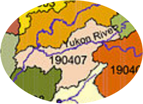
for this map, I would say this is the best method, because the image quality is not very good for auto-tracing. Please see the main tutorial for general advantages and disadvantages. I'll use this map of Alaska (below), to illustrate and explain the process.
- File menu > Import
For this particular image, I'm going to use the default rendering mode for raster images (auto). Because of the nice black borders, I can see the details better, this way. (For other images, without the bold borders, I might use the Blocky (optimize speed) option, because it will show the pixels when zoomed in. Seeing the pixels helps to identify the color changes, when there's not a nice dark line to follow.)
(Optionally, you may want to put the image in its own layer. This allows it to be locked, to prevent accidentally moving it. Also you can reduce the opacity of the layer, which you might find helpful during the tracing process.)
- Layers menu > Layers
- Click the blue plus sign (
 )
) - Enter a name for the layer (if you want something besides "Layer 2"), and choose Below Current, from the dropdown Position menu
- Click the Add button
- Select the imported image
- Hold the Shift key while you press PdDn once (moves the image into the new layer)
- Click the tiny open lock icon (changes to a closed lock icon) to lock the layer
- Drag the Opacity slider, to suit your needs
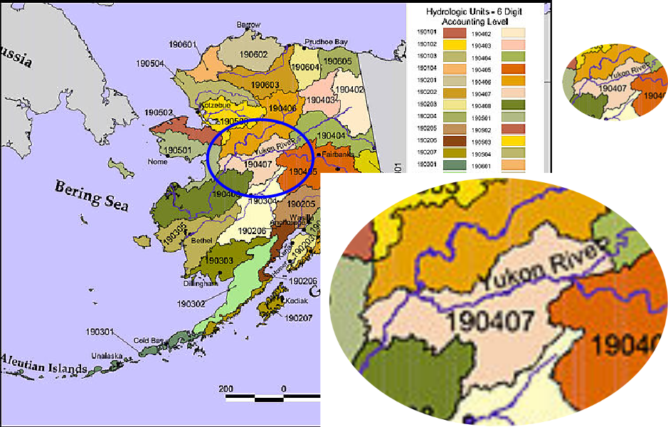
I'll be tracing that light pink shape in the middle of the state, circled in blue above, to demonstrate how you can maintain the fine detail, in your vector version. (I'm not sure if these are counties, or some other kind of district, so I'm calling them "shapes".) To save space, I've created a smaller version of the map (by using the blue circle to clip the map). So that small version is above-right. And below shows how far you'll need to be zoomed in, to do a good manual trace.
- Enable the Zoom tool (
 ), and drag a selection box around the area where you want to start
 - Enable the Pen/Bezier tool and make sure, on the control bar, that you're in either Regular Bezier mode, or Straight Line mode, and that the Shape dropdown menu is set for None
- Position your mouse over the black border, and click once to start your path
- Click once at every bend or corner along the border
If you misplaced a node, you can press the backspace key, to undo the last node you placed. You can press it repeatedly, if you need to go back a few clicks.
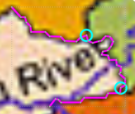
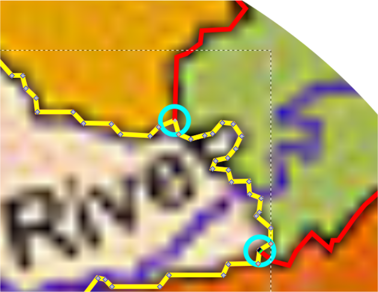
When you come to a place where the border of one of the neighboring shapes meets the border you're tracing (aqua-colored circles, right), make sure to place a single node. That's because later, that's where you'll need to break the path, to create a matching path for that neighboring shape.
- After you've clicked along for a short distance, double-click to end that section of the path (pink in my screenshots)
I like to work in this way, making a relatively long path in several shorter segments. But I tend to work quite slowly in Inkscape, compared to others. You'll develop your own preferences and tendencies, as you learn. Anyway, just so you'll know how, here's how to continue a path that's already started.
- Select the path with either the Selection tool or the Node tool, then switch to the Pen/Bezier tool
Now you can't see the nodes anymore (only with the Node tool) but you can see a tiny square at each end of the path (as on the left). I know the quality of the image isn't great. So if you can't make them out here, be sure to follow along on your own Inkscape canvas, where they will be easier to see.
- Position your mouse over one of these squares
If you look closely, you can barely notice it will turn red, when your mouse is in the proper position.
- Click once to continue the path
- Continue clicking around, until you come back to where you started, and click once inside the tiny square at the beginning, to close and end the path
Now that we have a path around one whole shape (just imagine that we do), we need to perform some techniques which come under the general heading of "node editing". There are basically 2 reasons for node editing, when tracing raster images. One, to make our new paths fit the curves in the image very, very closely. And second, to break paths and join paths together, to create the kind of closed paths that are needed.
For this image, since we're zoomed in so far, it's easy to place the nodes correctly on the first try. Also, these black borders are jagged, and we don't need smooth nodes and curves. But there will be a whole lot of breaking paths and joining paths, to create the closed paths we need. However, for some images, it's often the other way around (more editing to fit curves than editing to break and join paths or path segments).
Node Editing
I'll explain how to do node editing, rather than give specific steps for every node. That way, you can edit your paths wherever you see it's needed.
When you select the path with the Node tool ![]() , you'll be able to see the nodes. Click once on a single node to select it. To deselect it, either click another node, or click in any blank area of the canvas. There are a few ways to select more than one node:
, you'll be able to see the nodes. Click once on a single node to select it. To deselect it, either click another node, or click in any blank area of the canvas. There are a few ways to select more than one node:
- hold the Shift key while you click once on each node that you want to select
- click on the path between 2 nodes, to select those 2 nodes at once
- Ctrl + a selects all the nodes in the selected path
- drag a selection box around the nodes you want to select
- hold the Shift key while doing some combination of those - for example, drag a selection box around a group of nodes, hold the Shift key, while you drag another selection box around a different grouping of nodes; or drag a selection box around a grouping of nodes, then hold the Shift key while you individually click a few more; etc.
- holding the Shift key can allow you to remove nodes from a selection too - for example, do Ctrl + a to select all the nodes in the path, then while holding Shift, click a few individual nodes to deselect them, while leaving all the others still selected
On a white background, nodes are gray. When the mouse is over them, they are red, and when they are selected, they're blue. If there are different colored objects behind them, or the background is a different color, the node colors change to some contrasting color. So they are almost always quite visible.
There are 4 types of nodes, but most of the time, you'll be using 2 kinds. Corner/cusp nodes are diamond-shaped, and generally create sharp corners, although not always. Smooth nodes are square-shaped, and always create curves. End nodes are always corner/cusp nodes. Oh, and by the way -- starting with version 0.91, we can change the size of nodes, in Inkscape Preferences > Input Devices > Handles (yes, even for just a mouse).
Nodes can be moved by dragging them, just like dragging objects with the Selection tool. When one node is dragged, all the selected nodes will move together. If only one node is selected, then only that node moves. Nodes can also be moved using the arrow keys. Pressed an arrow key once will move selected nodes by 2 px (changeable in Inkscape Preferences). Holding the Alt key while pressing an arrow key once will move selected nodes by something less than 2 px, depending on the zoom level. (the higher the zoom level, the shorter the distance) Holding the Shift key while pressing an arrow key once will move selected nodes by 10 times 2 px (20 px).
When nodes are selected, their handles are revealed. As you can see in the screenshots above, handles are thin, straight, blue lines with tiny circles on the end. You can grab the tiny circle with the Node tool and drag the handles. That's how you can control the curves or corners. Corner/cusp nodes can have zero, 1, or 2 handles, which always move independently. Smooth nodes can have 1 or 2 handles, but most of the time it's 2, which always move together. If a smooth node only has 1 handle, it can't be moved, although I'm not sure why. (The node can be moved, but not handle.)
For this map image, I don't expect you would need to use many smooth nodes....maybe around the coastlines, where the curves look smoother. But generally in node editing, you may need to change node types often. To do that, just select the node or nodes that you need to change, and click either "Make selected nodes smooth" button ( ![]() ) or "Make selected nodes corner/cusp" button (
) or "Make selected nodes corner/cusp" button ( ![]() ), which are on the Node tool control bar. Or, as for almost everything, Inkscape offers key shortcuts. If you want to learn them, you can find in Help menu > Key and Mouse Reference.
), which are on the Node tool control bar. Or, as for almost everything, Inkscape offers key shortcuts. If you want to learn them, you can find in Help menu > Key and Mouse Reference.
Sometimes nodes don't have any handles, when you need a handle to make a curve. So you can, more or less, extract a handle from the node. Using the same dragging technique that you use to drag objects or nodes, position the mouse over the node (it will turn red, when you're in the proper position) press the mouse button and hold while you drag away from the node. You'll see the handle appear, and get longer, the further you drag it.
Or if you don't need a handle on a node, you can remove it. Position your mouse over the tiny circle, which wll also turn red when you're in the proper place (although it might be hard to notice, because the circle is so tiny). Press the Ctrl key and hold, while you click once. And boom, it disappears. However, note that when you remove the handles from a smooth node, it automatically becomes a corner/cusp node.
Ok, so all of the above info on node editing, is what you need to adjust the path to fit the curves very well. But what we'll use much more in this image, is breaking paths and joining paths together. This is how we can make the borders for each shape match precisely the border of the adjacent shape. For this, I'll use screenshots from the tracing I've done.
By now, I've traced a red path around that green shape to the right of the first (pink) one I traced. But I did not trace the part of the border where the pink path was, because we're going to use that pink path to make an identical section for the red path.
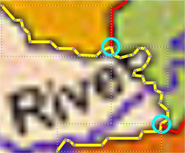
- Duplicate the entire pink path, and give it some other color, just to help keep things organized (mine is yellow, and that's why you can't see the pink path, in the screenshot above - but it's under there)
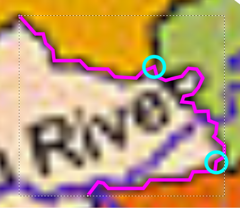
- Select the node on the yellow path where the top red path (of the green shape) meets it (in the top aqua circle)
- Click "Break path at selected nodes" button (
 ) on the Node tool control bar
In the screenshot above, you can see that the path is broken. Notice how the node there looks smaller than regular nodes? When any even number of nodes are stacked up precisely on top of each other, that's how the nodes look. You can only know exactly how many nodes might be stacked up there, by selecting them (drag a selection box with the Node tool) and looking at the status bar.
In this case, we know they are 2 there, because when a path is broken, there are 2 new end nodes in place of the one original node. If there is an odd number of nodes stacked up on each other, it looks like a regular single node. So that can be kind of tricky.
- Repeat steps #2 and #3 for the lower node
Note that if you've completed all the tracing (for that shape), you can select as many nodes as you need, wherever you're going to break the path, and break them all at once, with only 1 click on "Break path at selected nodes" button. I've only guided you to break these separately, so you can see another screenshot of a selected node with a non-white color behind it (the one in the bottom aqua circle), to show how they change color, if needed (above).
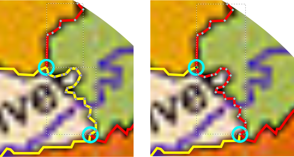
- After the path has been broken at both nodes, do Path menu > Break Apart
While we had already broken the path at those 2 nodes, the individual path segments were still sub-paths of a compound path. This step makes them entirely separate paths. Above you can see the yellow path, right after I broke the path apart into all its newly separated paths. And you can see in both of the aqua circles, the special node indicating that there are 2 overlapping nodes there.
- Select both red paths and duplicate them
- Deselect everything (click in any open area of the canvas)
- Select the middle yellow path and the top red path (click 1, then hold Shift while you click the other)
- Drag a selection box around the 2 overlapping end nodes
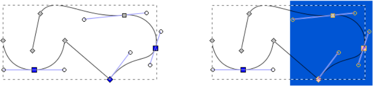
Notice in the screenshot below-left -- when 2 overlapping nodes are selected, they have the appearance of no nodes being there at all! That's how it looks when an even number of overlapping nodes is selected. If an odd number is selected, it looks like just 1 node is selected. Don't forget, you can always look at the status bar, to be sure.
- Click "Join selected nodes" button (
 ) on the Node tool control bar
Notice after you join the 2 paths together, below-right, that the new longer path takes the color of one or the other paths. I'm not sure what the rule is, for which color it takes. But of course, it's not big deal to change the path color to whatever you need.
- Select the new red path, and just to keep things clear, give it some different color than any we've already used....how about bright green
- Repeat steps #8, #9, and #10, to join the bottom red path to the new green path
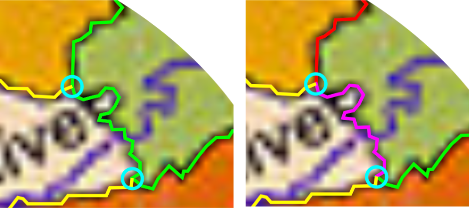
Now we have the new light-green path for the darker green shape, as you can see above-left. With the new light-green path selected, switch to the Selection tool. Click the "Lower selection by 1 step" button on the control bar a few times, until you can see the original pink path. So you can see that the shared border of both shapes are identical, where the 2 shapes meet, in the screenshot above-right. Another click or 2 to lower the green path a little more, and you can see that duplicates of the red paths are still there, and ready to be used for that side of the adjacent shapes (above and below the green shape).
So, that's about all you need to know for node editing. If you get stuck or you have questions, please feel free to post in the forum.
Auto-Trace Using Inkscape's Trace Bitmap
Of course, auto-tracing could be much faster than tracing by hand. But it depends on your needs and goals for the image, as well as the quality of the original, whether it would be the best choice. If this is to be your choice, the best type of file to use, would be as high resolution as possible.
Using the little version of the map I clipped out, let's try Trace Bitmap, and you will quickly be able to see the difference, and decide whether you could use it, or not. The screenshots below (from top to bottom) are: the original "little" version of the map, the settings for Trace Bitmap, and the results.
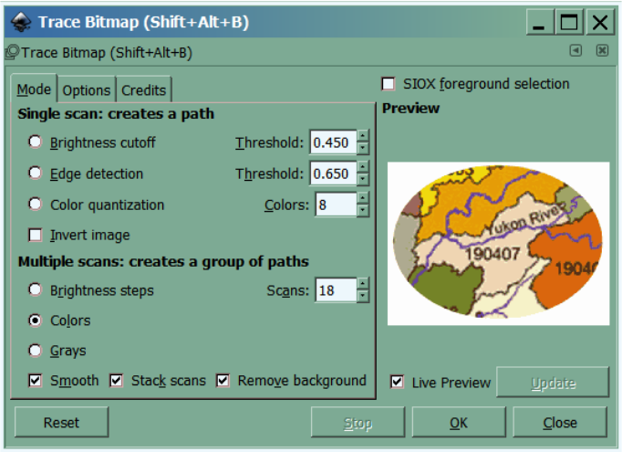
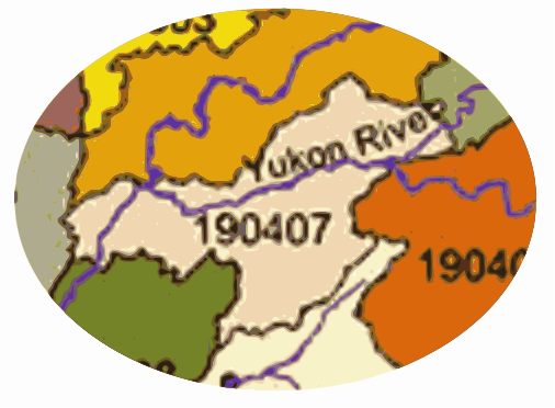
Referring to the trace result above, to have the trace turn out as close to the map as possible, I had to use 18 scans. So there are 18 objects, each is a different-colored compound path, all stacked up, to create the image that Inkscape sees. Let's look closely at the same area where we were working before.
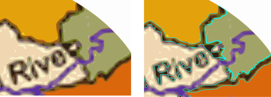
Even though the trace result, at 100% zoom, looks relatively pretty good; when zoomed in, it seems hardly recognizable. There is a fundamental difference between how the auto-trace is made, and how a hand-traced image is made.
Above-left is the auto-trace result. You can actually see many of the different-colored compound paths. Above-right, I placed an aqua-colored stroke on the object that seems to me to be the closest to what we might need for those black borders. That aqua stroke represents the actual compound path, for that color/object.
So, if you need the single path around each shape, as we made above, then auto-tracing the map is not a good option.
If you don't necessarily need a single path around each shape, and an auto-trace result would be generally acceptable, it is entirely possible to use Trace Bitmap on a map, assuming the raster map is of high enough quality.
Just to show an example of a map that is better suited for auto-tracing, let's trace this portion of a map of Canada. To save space, I've scaled it smaller. But as I said before, it's best to use as high resolution image as possible. You can see that it's not nearly as pixelated as the other map.
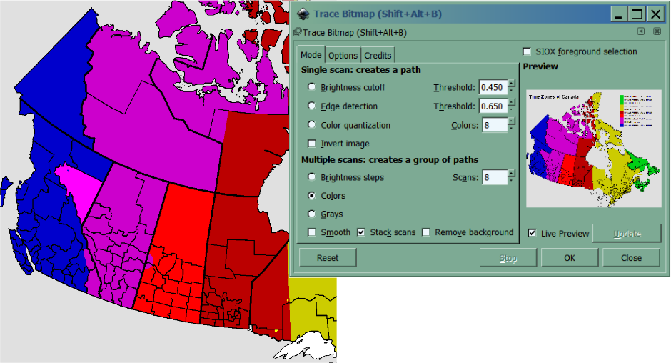
The options I used for the Trace Bitmap dialog are above.
And below-left is my result, also scaled smaller, to save space. Below-right is zoomed in, to see the details of the result.
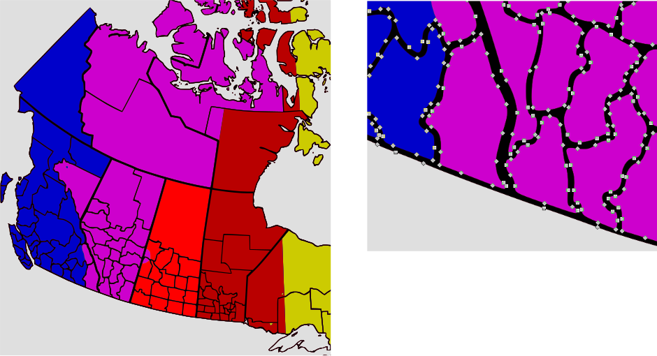
So you can see that we have a nice solid black object to define the spaces. However, there are no individual shapes this way. That compound black path lies on top of a whole purple object.
If you need help, or have any questions, please feel free to post in the forum.
brynn, November 2015